
Key Features
- Modular-design cutterbar
- Easy hookup to tractor drawbar
- Adjustable cutterbar angle
- Flotation tires
Features
 Clevis hitch
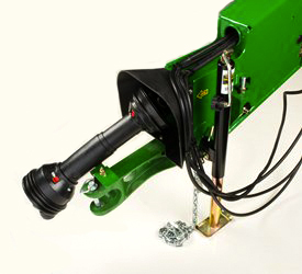
The clevis hitch is in base equipment. This design attaches directly to the tractor drawbar for operator convenience. The heavy-duty clevis design provides a strong attaching point to the drawbar.
For added convenience, the hitch-pin retaining bracket can also be used to store the power take-off (PTO) shaft when the machine is not attached to the tractor.
The clevis hitch is designed to be towed by a tractor only and includes a screw jack and safety chain.
Turn limiters may be required to prevent powerline damage if the hitch point of the tractor is beyond the rear drive wheels of the tractor.
 540-rpm overrunning and slip clutch
An overrunning clutch is located near the platform gearcase; this design enables free rotation of the tractor hookup to make attaching to the tractor easier.
A slip clutch is incorporated into the overrunning clutch to provide protection to the platform.
 Drawbar equal-angle hitch
 Drawbar extension
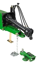
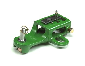
The drawbar equal-angle hitch is optional equipment. This hitch option includes:
-
Ball-joint hitch—to be installed on the mower-conditioner tongue
-
Tractor hookup
-
Drawbar extension—to be installed on the tractor drawbar and adjustable with one wrench
The drawbar equal-angle hitch is designed to be towed by a tractor only and includes a screw jack and safety chain.
Turn limiters may be required to prevent powerline damage if the hitch point of the tractor is beyond the rear drive wheels of the tractor.
540-rpm overrunning and slip clutch
An overrunning clutch is located near the platform gearcase. This design enables free rotation of the tractor hookup for easier attaching to the tractor.
A slip clutch is incorporated into the overrunning clutch to provide protection to the platform.
 Rotary cutterbar
The rotary cutterbar is designed and built by John Deere. Large oval disks with free-swinging knives are used to cut the crop.
All cutting disks are the same and are computer-designed for improved wear and cutting performance.
Cutting disks are made of high-strength, austempered steel to ensure the steel is thoroughly and evenly tempered for good wear characteristics.
The disks rotate to give a knife-tip speed of 307 km/h (191 mph) for clean cutting.
The knives are free-swinging to reduce damage if a solid object is struck, and they are reversible to double the useful life.
The knives are removed at the front of the cutterbar for convenience.
Wear caps
 Wear caps
Made of austempered, heat-treated, ductile steel for excellent wear characteristics, wear caps are installed on each end of the cutting disks (except on the end disks where crop accelerators are used) to increase the wear life of the cutting disks and knife-bolt nuts.
Wear caps are open on the end to prevent debris from packing in close to the nut, making hardware and knives easier to change.
 Modular cutterbar
John Deere's patented design cutterbar is made from individual, diagonal-cut modules.
Serviceability is easy. Modules can be removed individually while leaving the cutterbar attached to the frame.
Made of high-strength, nodular iron castings, each module consists of two idler gears and one drive gear. The large-diameter idler gears transmit power from module to module. The idler gears turn at a relatively slow speed for added durability.
The smaller-diameter pinion drive gear is used only to power the cutting disk. Power is not transmitted from one cutting disk to another except through the large-diameter idler gears.
The modules are interchangeable. Disk rotation is determined by the position of the quill (A). There is a rubber oil seal between each cutting module.
Tough enough for a three-year cutterbar warranty

The durable John Deere cutterbar comes standard with a three-year warranty on all 600 and 800 Series Mower Conditioners. This warranty covers all internal drive components, such as idler and pinion gears. Wear components, such as knives, wear caps, and shear hubs are not included in the warranty.
 Gauge shoe
Steel runners are located under each disk. Right-hand and left-hand adjustable gauge shoes further protect the cutterbar.
The half-moon shaped disk protectors extend past the cutterbar module to protect the cutting disk.
The disk protectors are made of heat-treated boron steel, whose material characteristics are very similar to spring steel. Resistance to bending is nearly three times greater than molded ductile iron.
Knives rotate close to the disk protectors to give a good shearing action and help to keep the cutterbar clean.
 Shearhub
Each cutting disk is attached to a driver (shearhub) on the splined pinion gear. The driver has part of its splines removed so it will shear if the cutting disk receives a severe impact.
The shear strength of the driver is designed to be just slightly less than that of the pinion gear.
Power to the disk is interrupted when the driver shears to protect the internal components of the cutterbar.
Damage is limited to exposed components and does not require disassembly of the cutting modules.
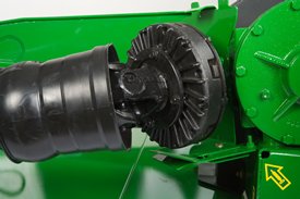
 U-joint
Power is transmitted through a U-joint to the first cutting disk.
The U-joint attaches with four bolts to the driver on the first cutting disk. No special tools are required to remove the first cutting disk.
The torque for attaching bolts is the same as for attaching the disk to the driver (149.1 Nm [110 lb-ft] compared to the 339 Nm [250 lb-ft] required to attach the driver to the pinion gear).
 Impeller conditioner
Impeller conditioning is standard equipment on all John Deere mower-conditioners.
Proper conditioning in a wide range of crops can be achieved when the conditioner is properly adjusted.
The impeller conditioner works well in legumes, especially alfalfa and most all-grass crops. Impeller conditioners are not recommended for thick-stemmed or cane-type crops, such as sudan or sudex, or crops over 1.5 m (5 ft) tall.
How an impeller conditioner works:
1. As hay is cut by rotating knives, tines pick up the plants and carry them through the machine:
- 33 V-shaped tines are on the 625 Mower-Conditioner; 45 V-shaped tines are on the 630 and 830 Mower-Conditioners; and 57 V-shaped tines are on the 635 and 835 Mower-Conditioners.
- Tines are free swinging to reduce damage to the conditioner if rocks or other solid objects are struck.
2. As the plant passes through, it rubs against the conditioning hood (A) and other plants:
Scuffing action removes the waxy surface from the stem of the plant to allow for faster evaporation of moisture.
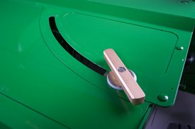
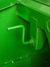 Impeller hood crank handle
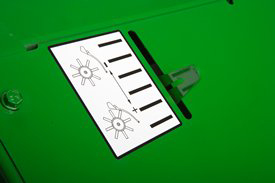 Impeller hood position indicator
- The conditioner hood opening is adjustable to accommodate various crop volumes.
- The crank handle allows an infinite number of adjustments between the minimum and maximum conditioning levels. The closer the hood is to the tines, the more aggressive the conditioning.
- A conditioner position indicator provides an easy reference point to control the degree of conditioning.
 630 Mower-Coonditioner (shown with shields removed)
3. The speed at which the tines rotate will also affect the degree of conditioning. Two impeller speeds can be achieved by interchanging the upper sheave (A), located under the shield, and the lower sheave (B).
- With the sheaves in the position shown, the impeller turns at 870 rpm; this is ideal for grasses.
- If the sheaves are reversed, the impeller turns at 630 rpm; this is ideal for legume crops.
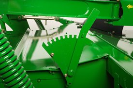
 Handle for forming-shield adjustment
Forming shields are easily adjusted to control material flow. This allows the operator to match the windrow width to harvesting requirements.
 Handle for swathboard adjustment
A swathboard is in base equipment for additional control of the windrow formation (for 630 and 635 Mower-Conditioner models only).
Windrow width* is as follows:
| 625 | 78.7 cm to 149.9 cm (31 in. to 59 in.) |
| 630 | 88.9 cm to 198.1 cm (35 in. to 78 in.) |
| 635 | 99 cm to 238.8 cm (39 in. to 94 in.) |
*Depending on crop conditions.

